Digger Derricks TMD Series by Versalift | Available at Versalift East
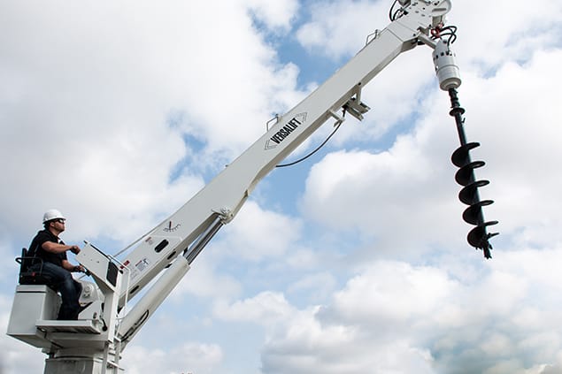
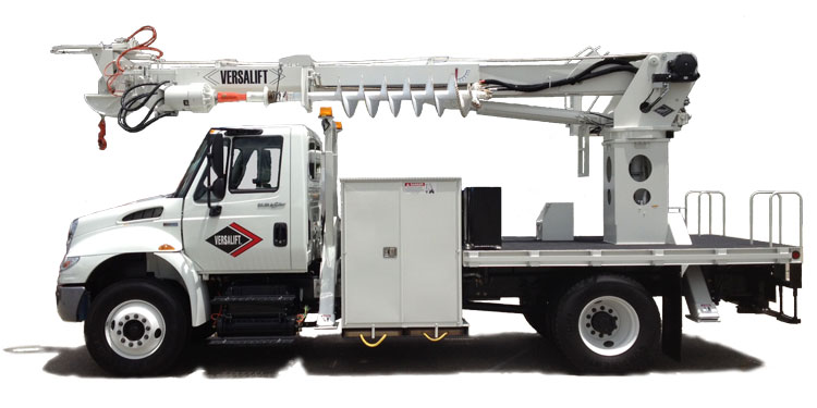
Digger Derricks support businesses and other organizations that manage large overhead systems, including telecommunications and electric power infrastructure. Versalift East is an authorized assembler, upfitter, servicer and distributor of Versalift bucket trucks, digger derricks and cable placers. For those organizations that build and repair overhead telecommunications and electric utility systems, Versalift digger derricks deliver a combination of power and reach in a range of sheave heights, and with a maximum sheave height of sixty feet.
Models
Details
Digger Derricks:
TMD-2042-B, TMD-2042-T, TMD-2045-B TMD-2045-T, TMD-2047-B, TMD-2047-T, TMD-2050-B, TMD-2050-T, TMD-4060-T
 |
 |
Digger Derricks Standard Specifications:
- This section includes a brief description of each of the TMD digger derrick major (standard) components.
- BOOM ASSEMBLY – The lower boom and intermediate boom is constructed of high strength steel. The upper boom is constructed of high strength, filament wound, epoxy resin. The extension system includes two double-acting hydraulic cylinders. Each cylinder incorporates dual counterbalance holding valves.
- BOOM LIFT CYLINDER – A single double-acting cylinder equipped with a counterbalance holding valve and self-aligning spherical bearing.
- ROTATION DRIVE – Consists of a hydraulically driven worm and spur gear acting on a shear ball rotation bearing. The gearbox incorporates a load sense feature to measure the side loads applied to the boom.
- TURNTABLE WINCH – The 15,000 lb maximum capacity turntable winch consists of a worm gearbox, hydraulic motor, holding valve, and drum. At 40 gpm flow, the winch provides an average line speed of 35 fpm.
- HYDRAULIC OVERLOAD PROTECTION – The overload protection is purely hydraulic and uses no electronics or electrical components. The system senses the boom lift cylinder pressure and side loads at the rotation gearbox. When an overload condition is detected, the system disables the following: digger dig, winch raise, boom lower, upper boom extend, and intermediate boom extend.
- CONTINUOUS ROTATION – Rotation is continuous and unrestricted in either direction.
- PINS, BEARINGS, AND LUBRICATION – The main pivot and cylinder joints use high strength hard chrome plated steel pins with fiberglass reinforced Teflon non-lube bearings.
- HYDRAULIC SYSTEM – Open center tandem system provides 40 gpm for the digger and winch circuit and 15 gpm for the boom functions. The digger/winch circuit operates at 2300 psi and the boom circuit operates at 2600 psi.
- INSULATION – The fiberglass is certified for 46kV and below in accordance with ANSI A10.31 dielectric rating requirements.
- 52 IN TALL PEDESTAL – The pedestal is a fabricated steel structure incorporating a 1.5” thick top plate which is machined flat to support the rotation bearing.
- DIGGER/WINCH PRESSURE GAGE – pressure gage on the lower control panel senses the pressure generated while using the digger and winch.
- BOOM PRESSURE GAGE – pressure gage on the lower control panel senses the pressure generated while using the boom control valve.
- CUSTOM LOAD CAPACITY CHART – Based on as built configuration.
- ENGINE START/STOP CONTROL – Operated by a toggle switch at the lower controls
- PAINTING – The complete unit is primed and painted prior to assembly. The standard color is white urethane.
- MANUALS – Two operator’s manuals and two service manuals are included.s
Digger Derrick Optional Specifications:
- This section contains a brief description of some of the numerous available options.
- TRANSFERABLE POLE GUIDE – Can be pinned to either the inner boom tip or the intermediate boom. The pole guide includes hydraulic tilt and hydraulic operation of the pole claws. Holding valves are included to lock both cylinders in position.
- POLE GUIDE INTERLOCK – Prevents inner boom from extending unless either of the following conditions is satisfied: 1. the pole guide tilt is fully raised. 2. Or the pole guide is properly pinned to the upper boom.
- WINCH LINE – Various winch lines are available including:
- 1” diameter x 100 ft. Stable Braid
- 1” diameter x 120 ft. Stable Braid
- 1” diameter x 120 ft. Amsteel II Plus
- SWIVEL HOOK– 5 ton, 8.5 ton, and 10 ton rated swivel hook are available.
- DOWNHAUL WEIGHT – Split ball downhaul designed to clamp to the winch line weighs approximately 50 lbs.
- DIGGER ASSEMBLY – Consists of the digger hanger and auger stow bracket. The digger hanger is automatically transferred from the lower boom to the intermediate boom when the auger is unstowed. The auger stow bracket includes an overstow protection valve.
- DIGGER DRIVES – Single speed digger drives are available in 6500, 8000, and 12000 ft-lb outputs. Two-speed drives are available in 8000 and 12000 ft-lb outputs. The Two-speed shift-on-the-fly drive is available in 12000 ft-lb output.
- AUGER STOW SLING – Available as a 3/8” diameter wire rope or a 7/8” diameter synthetic rope.
- AUGERS – Various augers are available.
- AUGER EXTENSION – 2-1/2” hex x 72” long
- RIDING SEAT LOWER CONTROLS WITH SINGLE STICK – Consists of a turntable mounted deck, seat, and control console. Includes full pressure, full flow hydraulic controls with a single handle joystick for boom raise-lower, rotate, and intermediate boom extend-retract. Additional hydraulic valve levers are included to control winch, dig, upper boom extend, pole guide tilt, and pole claw open-close.
- PANEL LIGHT – Two 12VDC lights help illuminate the lower control panel.
- HYDRAULIC TOOLS AT BASE – Consists of a ship-loose hydraulic tool selector valve and a flow/pressure control valve. The tool pressure can be adjusted from 750 to 2500 psi and the pressure compensated flow control can be adjusted from 0 to 8 gpm.
- SUB-FRAME – The full length subframe is constructed of 6 x 6 square tubing and 5/16” plate. The pedestal mounts above the subframe allowing for possum belly storage. Shear plates are provided to attach to the vehicle frame.
- MAIN A-FRAME OUTRIGGERS – A-frame outriggers are designed and constructed from high-strength steel. Outriggers are equipped with pilot operated check valves, internal thermal relief valves, and separate operating controls for each outrigger. Slide pads at each leg ensure smooth operation. The standard pivot feet swivel a minimum of 100 each way.
- AUXILIARY A-FRAME OUTRIGGERS – A-frame outriggers are designed and constructed from high-strength steel. Outriggers are equipped with pilot operated check valves, internal thermal relief valves, and separate operating controls for each outrigger. Slide pads at each leg ensure smooth operation. The standard pivot feet swivel a minimum of 100 each way.
- HYDRAULIC PUMP – Tandem gear pump supplies 15 and 25 gpm, which combine for 40 gpm.
- OIL RESERVOIR – 50 gallon bulkhead mount reservoir. Includes cleanout, 10 micron return filter that can be replaced without draining the reservoir, dipstick, 100 mesh (149 micron) suction screen, gate valve, and magnetic drain plug.
- THROTTLE CONTROL – Variable speed foot operated pedal used to control the engine speed from the lower control station.
- OUTRIGGER/BOOM INTERLOCK – The outrigger/boom interlock system is designed to prevent the boom from operating until the outriggers contact the ground. It also prevents the outriggers from being retracted before the boom is properly stowed.
- 6” TALLER PEDESTAL – Provides additional cab clearance.
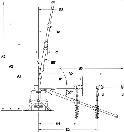
TMD-2042/2045/2047/2050T
DIGGER DERRICKS – DIMENSIONAL SPECIFICATIONS
(All values nominal)
Hydraulic System
| Operating Pressure (booms) | 2600 psi (183 kg/cm2) |
| Operating Pressure (digger/winch) | 2300 psi (162 kg/cm2) |
| Hydraulic Flow Rate (booms) | 15 gpm (57 lpm) |
| Hydraulic Flow Rate (digger/winch) | 40 gpm (151 lpm) |
| Filtration | 10 micron Return/100 mesh Suction |
| System Type | Open Center |
| Power Source | PTO Pump |
Boom Action
| Boom Articulation | -20 to +80° |
| Rotation | 360° continuous |
Range Chart Dimensions
| Model | Maximum
Capacity*
|
Capacity at
10′ Radius*
|
Horizontal Reach | Sheave Height | Load Radius | Digging Radius | |||||||
|
B1
|
B2
|
B3
|
A1
|
A2
|
A3
|
R1
|
R2
|
R3
|
S1
|
S2
|
|||
| TMD-2042T |
27800 lb
12610 kg |
12400lb
5620 kg |
16.8 ft
5.1 m |
24.8 ft
7.6 m |
32.8 ft
10.0 m |
27.4 ft
8.4 m |
35.3 ft
10.8 m |
43.2 ft
13.2 m |
3.6 ft
1.1 m |
5.0 ft
1.5 m |
6.3 ft
1.9 m |
14.3 ft
4.4 m |
22.3 ft
6.8 m |
| TMD-2045T |
26400 lb
11970 kg |
12100 lb
5490 kg |
17.8 ft
5.4 m |
26.8 ft
8.2 m |
35.8 ft
10.9 m |
28.4 ft
8.7 m |
37.3 ft
11.4 m |
46.1 ft
14.1 m |
3.7 ft
1.1 m |
5.3 ft
1.6 m |
6.9 ft
2.1 m |
15.3 ft
4.7 m |
24.3 ft
7.4 m |
| TMD-2047T |
23900 lb
10840 kg |
11600 lb
5260 kg |
19.8 ft
6.0 m |
28.8 ft
8.8 m |
37.8 ft
11.5 m |
30.4 ft
9.3 m |
39.3 ft
12.0 m |
48.1 ft
14.7 m |
4.1 ft
1.2 m |
5.6 ft
1.7 m |
7.2 ft
2.2 m |
17.3 ft
5.3 m |
26.3 ft
8.0m |
| TMD-2050T |
23900 lb
10840 kg |
11600 lb
5260 kg |
19.8 ft
6.0 m |
30.3 ft
9.2 m |
40.8 ft
12.4 m |
30.4 ft
9.3 m |
40.7 ft
12.4 m |
51.1 ft
15.6 m |
4.1 ft
1.2 m |
5.9 ft
1.8 m |
7.7 ft
2.3 m |
17.3 ft
5.3 m |
27.8 ft
8.5 m |
*Capacity varies with options
MINIMUM VEHICLE SPECIFICATIONS TMD-2042/2045T
| Frame Section Modulus | 18 in3 (295 cm3) |
| Frame Resisting Bending Moment | 900,000 in-lbs (1020000 N-m) |
| Cab to Rear Axle Dimension | 102 in (2.59 m) |
| GVWR | 31,000 lbs (14060 kg) |
| GAWR (FRONT) | 12,000 lbs (5440 kg) |
| GAWR (REAR) | 19,000 lbs (8620 kg) |
| Curb Weight for Stability | 25,000 lbs (11340 kg) |
MINIMUM VEHICLE SPECIFICATIONS TMD-2047/2050T
| Frame Section Modulus | 18 in3 (295 cm3) |
| Frame Resisting Bending Moment | 900,000 in-lbs (1020000 N-m) |
| Cab to Rear Axle Dimension | 120 in (3.05 m) |
| GVWR | 31,000 lbs (14060 kg) |
| GAWR (FRONT) | 12,000 lbs (5440 kg) |
| GAWR (REAR) | 19,000 lbs (8620 kg) |
| Curb Weight for Stability | 25,500 lbs (11560 kg) |